|
|
|
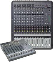
Sound mixers (AKA sound desks, sound consoles or sound
boards) are amongst the most common type of equipment in the world of audio
production. Every sound operator must know what a sound mixer is and how to use
it. The tutorials below cover the general layout and functions of sound mixing
devices.
Each input source comes into the mixer through a channel. The more channels
a mixer has, the more sources it can accept. The following examples show some
common ways to describe a mixer's compliment of channels:
|
12-channel |
12 input channels. |
|
16x2 |
16 input channels, 2 output channels. |
|
24x4x2 |
24 input channels, 4 subgroup channels and two output
channels. |
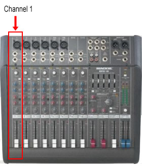 Input Channels
On most sound desks, input channels take up most of the space. All those
rows of knobs are channels. Exactly what controls each channel has depends on
the mixer but most mixers share common features. The list below details the
controls available on a typical mixer channel.
Input Gain / Attenuation: The level of the signal as it enters the
channel. In most cases this will be a pot (potentiometer) knob which adjusts
the level. The idea is to adjust the levels of all input sources (which will be
different depending on the type of source) to an ideal level for the mixer.
There may also be a switch or pad which will increase or decrease the level by
a set amount (e.g. mic/line switch).
Phantom Power: Turns phantom power on or
off for the channel.
Equalization: Most mixers have at least two EQ controls (high and low
frequencies). Good mixers have more advanced controls, in particular, parametric
equalization.
See also: Audio
equalization.
Auxiliary Channels: Sometimes called aux channels for short,
auxiliary channels are a way to send a "copy" of the channel signal
somewhere else. There are many reasons to do this, most commonly to provide
separate monitor feeds or to add effects (reverb etc).
Pan & Assignment: Each channel
can be panned left or right on the master mix. Advanced mixers also allow the
channel to be "assigned" in various ways, e.g. sent directly to the
main mix or sent only to a particular subgroup.
Solo / Mute / PFL: These switches control how the channel is
monitored. They do not affect the actual output of the channel.
Channel On / Off: Turns the entire channel on or off.
Slider: The level of the channel signal as it leaves the channel and
heads to the next stage (subgroup or master mix).
Larger sound desks usually have a set of subgroups, which provide a
way to sub-mix groups of channels before they are sent to the main output mix.
For example, you might have 10 input channels for the drum mics
which are assigned to 2 subgroup channels, which in turn are assigned to the
master mix. This way you only need to adjust the two subgroup sliders to adjust
the level of the entire drum kit.
The first point of each channel's pathway is the input socket, where the
sound source plugs into the mixer. It is important to note what type of input
sockets are available — the most common types are XLR,
6.5mm
Jack and RCA.
Input sockets are usually located either on the rear panel of the mixer or on
the top above each channel.
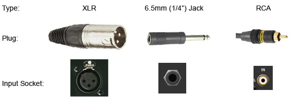
There are no hard-and-fast rules about what type of equipment uses each type
of connector, but here are some general guidelines:
|
XLR |
Microphones and some audio devices. Usually balanced audio, but XLRs can also accommodate unbalanced
signals. |
|
6.5mm Jack |
Musical instruments such as electric guitars, as well as
various audio devices. Mono jacks are unbalanced, stereo jacks can be either
unbalanced stereo or balanced mono. |
|
RCA |
Musical devices such as disc players, effects units, etc. |
Note: For more information see Audio Connections.
The level of an audio signal refers to the voltage level of the
signal. Signals can be divided into three categories: Mic-level
(low), line-level (a bit higher) and loudspeaker-level (very
high). Microphones produce a mic-level signal,
whereas most audio devices such as disc players produce a line-level signal.
Loudspeaker-level signals are produced by amplifiers and are only appropriate
for plugging into a speaker — never plug a loudspeaker-level signal into
anything else.
Sound mixers must be able to accommodate both mic-level
and line-level signals. In some cases there are two separate inputs for each
channel and you select the appropriate one. It is also common to include some
sort of switch to select between inputs and/or signal levels.
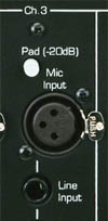 Input
Sockets and Controls
Input
Sockets and ControlsThe example on the right shows the input connections on a typical mixer.
This mixer has two input sockets — an XLR for mic-level
inputs and a 6.5mm jack for line-level inputs. It also has a pad button
which reduces the input level (gain) by 20dB. This is useful when you have a
line-level source that you want to plug into the mic
input.
Some mixers also offer RCA inputs or digital audio inputs for each channel.
Some mixers provide different sockets for different channels, for example, XLR
for the first 6 channels and RCA for the remainder.
When a signal enters the mixer, one of the first controls is the input gain.
This is a knob which adjusts the signal level before it continues to the main
parts of the channel. The input gain is usually set once when the source is
plugged in and left at the same level — any volume adjustments are made by the
channel fader
rather than the gain control.
Set the gain control so that when the fader is at 0dB the signal is peaking
around 0dB on the VU
meters.
Phasing: Some equipment and cables are wired with
different phasing, that is, the wires in the cable which carry the signal are
arranged differently. This will kill any sound from that source. To fix
this problem, some mixers have a phase selector which will change the
phasing at the input stage.
Phantom Power: Some mixers have the option to provide a small voltage
back up the input cable to power a microphone or other device. See Phantom Power for
more information.
 Most
mixers have some of sort equalization controls for each channel. Channel
equalizers use knobs (rather than sliders), and can be anything from simple
tone controls to multiple parametric controls.
Most
mixers have some of sort equalization controls for each channel. Channel
equalizers use knobs (rather than sliders), and can be anything from simple
tone controls to multiple parametric controls.
Note: For more general information about equalization see Audio Equalizers.
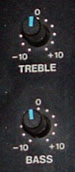
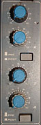
The first example on the right is a simple 2-way equalizer, sometimes
referred to as bass/treble or low/high. The upper knob adjusts high frequencies
(treble) and the lower knob adjusts low frequencies (bass). This is a fairly
coarse type of equalization, suitable for making rough adjustments to the
overall tone but is not much use for fine control.
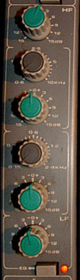 This
next example is a 4-way equalizer. The top and bottom knobs are simple high and
low frequency adjustments (HF and LF).
This
next example is a 4-way equalizer. The top and bottom knobs are simple high and
low frequency adjustments (HF and LF).
The middle controls consist of two pairs of knobs. These pairs are parametric
equalizers — each pair works together to adjust a frequency range chosen by
the operator. The brown knob selects the frequency range to adjust and the
green knob makes the adjustment.
The top pair works in the high-mid frequency range (0.6KHz
to 10KHz), the lower pair works in the low-mid range (0.15 to 2.4KHz).
The "EQ" button below the controls turns the equalization on and
off for this channel. This lets you easily compare the treated and untreated
sound.
It is common for mixers with parametric equalizers to combine each pair of
knobs into a single 2-stage knob with one on top of the other. This saves space
which is always a bonus for mixing consoles.
If the mixer provides good parametric equalization you will usually find
that these controls are more than adequate for equalizing individual sources.
If the mixer is limited to very simple equalization, you may want to use
external equalizers. For example, you could add a graphic equalizer to a
channel using the insert feature.
In many situations you will use additional equalization outside the mixer.
In live sound situations, for example, you will probably have at least one
stereo graphic equalizer on the master output.
Most sound desks include one or more auxiliary channels (often
referred to as aux channels for short). This feature allows you to send
a secondary feed of an input channel's
audio signal to another destination, independent of the channel's main output.
The example below shows a four-channel mixer, with the main signal paths
shown in green. Each input channel includes an auxiliary channel control knob —
this adjusts the level of the signal sent to the auxiliary output (shown in
blue). The auxiliary output is the sum of the signals sent from each channel.
If a particular channel's auxiliary knob is turned right down, that channel is
not contributing to the auxiliary channel.
In the example above, the auxiliary output is sent to a monitoring system.
This enables a monitor feed which is different to the main output, which can be
very useful. There are many other applications for auxiliary channels,
including:
Mixers are not limited to a single auxiliary channel,
in fact it is common to have up to four or more. The following example has two
auxiliary channels — "Aux 1" is used for a monitor and "Aux
2" is used for an effects unit.
Note that the monitor channel (Aux 1) is "one way", i.e. the
channel is sent away from the mixer and doesn't come back. However the Aux 2
channel leaves the mixer via the aux send output, goes through the
effects unit, then comes back into the mixer via the aux return input.
It is then mixed into the master stereo bus.
 The
auxiliary output from each channel can be either pre-fader or post-fader.
The
auxiliary output from each channel can be either pre-fader or post-fader.
A pre-fader output is independent of the channel fader, i.e. the
auxiliary output stays the same level whatever the fader is set to.
A post-fader output is dependent on the fader level. If you turn the
fader down the auxiliary output goes down as well.
Many mixers allow you to choose which method to use with a selector button. The
example pictured right shows a mixer channel with four auxiliary channels and
two pre/post selectors. Each selector applies to the two channels above it, so
for example, the button in the middle makes both Aux 1 and Aux 2 either
pre-fader or post-fader.
One of the last sets of controls on each channel,
usually just before the fader, is the channel assign and pan.
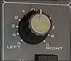 Pan
PanAlmost all stereo mixers allow you to assign the amount of panning. This is
a knob which goes from full left to full right. This is where the channel
signal appears on the master mix (or across two subgroups if
this is how the channel is assigned). If the knob is turned fully left, the
channel audio will only come through the left speaker in the final mix. Turn
the knob right to place the channel on the right side of the mix.
This option may be absent on smaller mixers but is quite important on large
consoles. The assign buttons determine where the channel signal is sent.
In many situations the signal is simply sent to the main master output. In
small mixers with no assign controls this happens automatically.
However you may not want a channel to be fed directly into the main mix. The
most common alternative is to send the channel to a subgroup first. For
example, you could send all the drum microphones to their own dedicated
subgroup which is then sent to the main mix. This way, you can adjust the
overall level of all the drums by adjusting the subgroup level.
 In
the example pictured right, the options are:
In
the example pictured right, the options are:
For stereo applications it is common to use subgroups in pairs to maintain
stereo separation. For example, it is preferable to use two subgroups for the
drums so you can pan the toms and cymbals from left to right.
You can assign the channel to any combination of the available options.
In some cases you may not want the channel to go to the main mix at all. For
example, you may have a channel set up for communicating with the stage via an aux
channel. In this case you don't assign the channel anywhere.
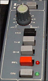
PFL
means Pre-Fade Listen. It's function is to do
exactly that — listen to the channel's audio at a point before the fader takes
effect. The PFL button is usually located just above the channel fader. In the
example on the right, it's the red button (the red LED lights when PFL is engaged).
Note: PFL is often pronounced "piffel".
When you press the PFL button, the main monitor output will stop monitoring
anything else and the only audio will be the selected PFL channel(s). This does
not affect the main output mix — just the sound you hear on the monitor bus. Note that all
selected PFL channels will be monitored, so you can press as many PFL buttons
as you like.
PFL also takes over the mixer's VU meters.
PFL is useful when setting the initial input gain
of a channel, as it reflects the pre-fade level.
PFL is similar to the solo button. There are two differences:
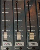 Each channel has it's
own fader (slider) to adjust the volume of the channel's signal before it is
sent to the next stage (subgroup or master mix).
Each channel has it's
own fader (slider) to adjust the volume of the channel's signal before it is
sent to the next stage (subgroup or master mix).
A slider is a potentiometer, or variable resistor. This is a
simple control which varies the amount of resistance and therefore the signal
level. If you are able to look into the inside of your console you will see
exactly how simple a fader is.
As a rule it is desirable to run the fader around the 0dB mark for optimum
sound quality, although this will obviously vary a lot.
Remember that there are two ways to adjust a channel's level: The input gain
and the output fader. Make sure the input gain provides a strong signal level
to the channel without clipping and leave it at that level — use the fader for
ongoing adjustments.
Subgroups are a way to "pre-mix" a number of channels on a sound
console before sending them to the master output mix. In the following diagram,
channels 1 and 2 are assigned directly to the master output bus. Channels 3,4,5 and 6 are assigned to subgroup 1, which in turn is
assigned to the master output.
Subgroups have many uses and advantages, the most obvious being that you can
pre-mix (sub-mix) groups of inputs.
For example, if you have six backing vocalists you can set up a good mix
just for them, balancing each voice to get a nice overall effect. If you then
send all six channels to one subgroup, you can adjust all backing vocals with a
single subgroup slider while still maintaining the balance between the
individual voices.
Note that if your mixing console's subgroups are mono, you will need to use
them in pairs to maintain a stereo effect. For each pair, one subgroup is the
left channel and the other is right. Each channel can be panned across the two
subgroups, while the subgroups are panned completely left and right into the
master output bus.
The main output from most mixing devices is a stereo output, using two
output sockets which should be fairly obvious and easy to locate. The
connectors are usually 3-pin XLRs on larger consoles, but can also be 6.5mm TR
(jack) sockets or RCA
sockets.
The level of the output signal is monitored on the mixer's VU meters. The
ideal is for the level to peak at around 0dB or just below. However you should
note that the dB scale is relative and 0dB on one mixer may not be the same as
0dB on another mixer or audio device. For this reason it is important to
understand how each device in the audio chain is referenced, otherwise you may
find that your output signal is unexpectedly high or low when it reaches the
next point in the chain.
In professional circles, the nominal level of 0dB is considered to be +4 dBu. Consumer-level equipment tends to use -10 dBV.
The best way to check the levels of different equipment is to use audio test tone. Send 0dB
tone from the desk and measure it at the next point in the chain.
Many mixers include a number of additional outputs, for example:
Monitor Feed: A dedicated monitor feed which can be adjusted
independently of the master output.
Headphones: The headphone output may be the same as the monitor feed,
or you may be able to select separate sources to listen to.
Auxiliary Sends: The output(s) of the mixer's auxiliary channels.
Subgroup Outputs: Some consoles have the option to output each
subgroup independently.
Communication Channels: Some consoles have additional output channels
available for communicating with the stage, recording booths, etc.